Reef aquarium
A well maintained reef aquarium can be a truly stunning sight and a stunning saltwater aquarium with fish, corals and invertebrates is a dream for many aquarists. Keeping a marine reef aquarium does not have to be hard and here at reefaquarium.com, we provide you with the information you need to keep different types of marine critters happy and healthy.
- We feature beginners guides that will help you set up and maintain your first reef aquarium. More experienced reef keepers will find in-depth articles that help them take their aquariums to the next hobby.
- We feature species guides that help you choose the right marine species for your aquarium.
- You will also find a lot of DIY articles that will help you save money by building aquariums and equipment yourself.
The name of the website is Reefaquarium.com but we feature information on all types of saltwater aquariums. We want to provide the resources you need regardless of whether you want to set up a fish only aquarium, a fish with live rock aquarium (FOWLR), planted saltwater aquariums or a full-blown reef aquarium.
Fish only aquariums, fish with live rock aquariums (FOWLR), planted saltwater aquariums can be a great way to learn the skills needed to one day keep a reef aquarium but they can also be stunning, fascinating aquariums in their own right. That is one of the reasons why most, not to say all, dedicated reef aquarium keepers also keep FOWLR aquariums.
Saltwater aquarium fish
Fish are some of the easiest creatures that you can keep in a saltwater aquarium and most people start their saltwater journey with a fish-only saltwater aquarium. There are of course many reef fish species that require very advanced care to do well in an aquarium but there is also a lot of hardy species that are suitable for beginners. You should always choose easy to care for hardy species when you set up your first marine aquarium. Species that can survive even if you make a mistake of two. You should of course always strive to give your fish the best home possible but everyone does mistakes when first learning how to keep saltwater fish.
There are many easy to care for species that are suitable for your first aquarium. Among these, you will find many stunning Damsel species, common clownfish, powder blue tang (Dory) and many other species. Take a look at our beginners’ page to find examples of good species for beginners. All species that we recommend on that page is hardy, easy to find in the aquarium trade and is commercially bred in large quantities for the pet industry. It is always best to get captive-bred fish whenever possible. That way the wild populations will remain strong.
Make sure to read as much as possible before you set up your first marine aquarium. If you never kept an aquarium before it can be good to start with a freshwater aquarium before you graduate to marine aquariums and in time to a reef aquarium, Freshwater aquariums are easier to keep and are cheaper to set up.
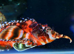
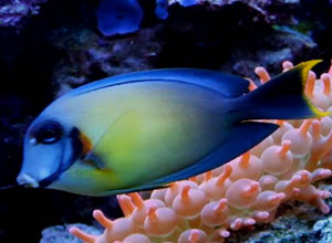
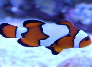
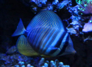
Popular reef aquarium fish
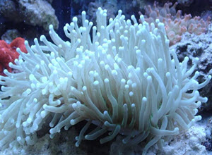
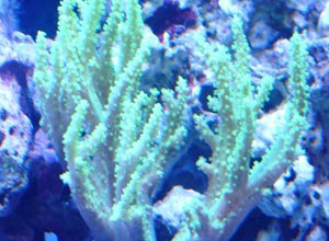
Corals for reef aquariums
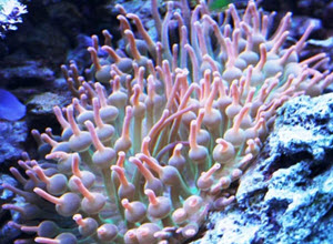
The use of soft and hard corals is what really sets a reef aquarium apart from other types of aquariums. A reef aquarium can use corals allows for every inch of the aquarium to be teaming with different types of life and colour. It is possible to achieve a similar result with plants in a freshwater aquarium but plants do not offer the variety in form and colour that corals offer. Expert reef keepers can even use macroalgae to introduce extra colour into their tanks.
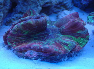
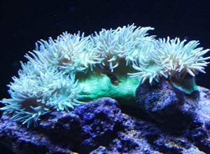
There is a very large selection of corals available on the market today and many corals can be very expensive. It is not unusual to see small coral fragments of less than an inch sell for several hundred dollars. Setting up a reef aquarium with a lot of exclusive corals can therefore become very expensive. It can also be very profitable if you are able to get the corals to thrive and you chose to propagate them.
Many coral species can be very sensitive and they can be a challenge to keep. They need the right light conditions, the right water flow, the right water parameters and the right food to do well. You will also have to make sure that they do not end up fighting other corals. (Yes coral wage war and a slow-growing species can kill and grow over a slower growing species if you do not keep an eye on them.) We recommend that you start by getting cheaper more robust coral species for your first aquarium. You can gradually buy more expensive types as you become more skilled at keeping them,
Luckily there are a number of readily available easy to care for corals. A few examples of such corals include Leather corals, Duncan corals and frogspawn corals.
Read more about corals in our coral section.
Popular Corals for reef aquariums
Invertebrates for reef aquariums
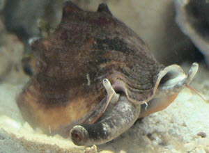
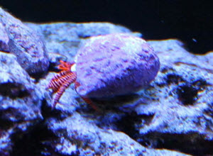
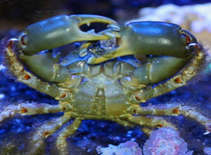
Invertebrates fill an important function in all reef aquariums and we recommend that you keep invertebrates in all saltwater aquariums. The reason for this is that invertebrates can be a very good clean up crew (CUC) for your aquarium. Invertebrates such as snails, shrimp and crabs can get into the small crevices in your tank and clean up all food that ends up uneaten by the fish. It is always a good idea to have a cleanup crew consisting of invertebrates in all tanks. How large clean up grew you need depends on how large your aquarium is.
Invertebrates do not only serve an important function in your aquarium. They can also be very beautiful and interesting additions to your aquarium. There are countless beautiful invertebrates available in well stock saltwater aquarium stores. A few examples of popular and stunning marine invertebrate species include the peppermint shrimp, the blood-red fire shrimp, the sexy anemone shrimp and the harlequin shrimp.
Popular Invertebrates
Is a reef aquarium worth the effort
Setting up and keeping a reef aquarium can seem like an overwhelming task when you first start to read of all the equipment you need to buy and all the care that is required to keep a thriving reef. I can however promise you that it is worth all the effort it takes to set up your first saltwater aquarium. I recommend that you start by setting up a fish-only saltwater aquarium (with some invertebrates to help keep it clean. Once you feel that you have learned enough you can ad live rocks to the tank to turn it into a Fish-only with live rock aquarium. Once your FOWLR aquarium has established itself well you can start adding corals to it and slowly turn it into a reef aquarium at whatever page you and your wallet feel comfortable with. This way you can learn as you go along and I promise you that you will love every step of the journey. Make sure that you start with an aquarium that is large enough to be turned into a reef aquarium. If you start with an aquarium that is too small you might have to set up a new aquarium when you want to take the next step of your journey. Although this might not be a bad thing since most fish keepers end up keeping several aquariums before they know it.
Good Resources
Below you will find links to different resources that I think are worth highlighting. These websites can help you when you want to get an aquarium or afford an update to a bigger aquarium. This is only a small selection of the websites we recommend. You can find a larger selection of recommended resources on our Resource page:
Daytrading is a website about trading and investing. It is my go-to when I discover financial terms that I do not understand. Daytrading.com have helped me make more money from my investments. Money I have invested wisely in new fish and tanks.
Aquatic Community is our sister site. There you can find information about all types of tropical fish. The main focus is on freshwater fish but the website also features a large marine section. Please feel free to visit our forum.
Investing.co.uk is a UK based investment website that features information on most trading related topics. It is a good stop when I want to know more about local trading regulations surrounding financial instruments such as CFDs and CFD brokers.
Reef builders is )in my opinion) the best source of saltwater aquarium news. They feature daily articles about new equipment, new captive bred species and unique on of a kind fish.
Safety
Remember that reef tanks are very heavy and filled with water. It is important that you consider safety issues before you place and set up a marine tank. You will need to choose a place where the floor is strong enough to support the weight of the tank. A large tank can weigh several thousand pounds. The weight of the tank might cause damage to your floor if the floor is not strong enough to support the tank. In a worst-case scenario, the aquarium can fall through the floor. It is also important to remember that your reef tank will be filled with water and that water can cause water damage if the aquarium breaks. This is rare but can happen. Either due to the aquarium being old or due to it being accidentally hit by something. There is also a risk that the plumbing of the tank starts leaking. Make sure that you have home insurance that cover water damage if your aquarium ever starts leaking.
Interviews